Discuss Launched Gliders (DLGs) are my favorite type of RC glider aircraft. They have no propulsion system, no motor or propeller. To launch, you spin in a circle and throw the plane into the air by hand, and then try to hack the wind and thermal activity to stay aloft as long as possible. It’s a ton of fun and you can spend a whole summer afternoon addictively launching and hunting thermals. I’ve wanted to build another DLG after I broke the wing on my last one (the one in the gif, in fact) – 10 years ago! Since it’s winter now, it’s building season, and I wanted to share the details of this Malibu DLG that I recently built.

Beware, building a DLG is an intense process, normally reserved for mid-level to expert builders. You really need a full shop of tools, a boatload of patience, and a painters / fine arts mindset to complete this artwork of a kit. This is the opposite of a beginner’s RC endeavor, and you’ll see why. Throughout this process, I made a few mistakes and things simply went wrong that I wasn’t expecting, and I hope that sharing this will be useful to any aspiring DLG builders out there who are ready to take the plunge. Improvisation and skill with hand tools, glues, and building techniques is a must – yet all very learn-able, as I am self-taught, and I hope this post helps teach someone out there!
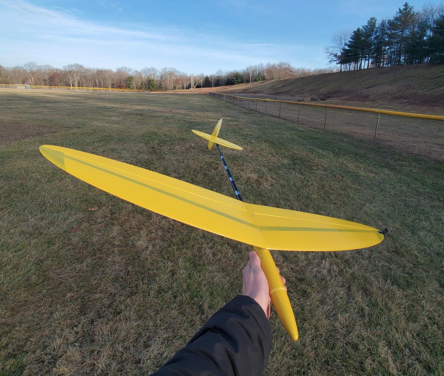
I’ll be showing you how I built this yellow DLG.
Building a DLG kit is rewarding, but there are options to buy ready-made ones for an extra price (ex. from ArmSoar). If you have the money and simply want to get in the air, I’d recommend buying a prebuilt DLG outright, either used locally or brand new. Note: you can’t ship a built DLG – they don’t come apart easily and the tail is too fragile since it’s so light – even new unassembled kits may come encased in wooden enclosures for shipping. DLG purchasing options are slim these days, but the internet should help point you in the right direction. Here is one DLG kit seller and another. There are cheaper foam DLGs, but they lack the thermalling performance and launch height capability that the regular ones do, so do your research before skimping out on a cheap glider.
It is a sad thing that DLGs are so expensive, delicate, and have such a difficult build process, since DLG is genuinely the most rewarding and addicting type of RC flying I’ve ever experienced. If more people could jump into this niche of the hobby, surely it would gain more mainstream RC traction. A lot of RC pilots who discover DLG end up exclusively flying DLGs before they realize it, and the rest of their fleet sits.
This is a long post with tons of pictures. I’ve purposefully added a lot of details and left these pictures large so that you can zoom in if necessary to see what I’ve done to solve certain problems. I performed this work over two days a week apart, spending about 4 hours the first day and around 6 the second day to finish it all up – of course, I hit a few problems along the way that slowed things down… you will see. Let’s begin!
(To see a build log for a 1.5m DLG (the standard size), see my TopSky build page).
Malibu 1m DLG
The DLG I chose to build is called the Malibu. It has a 1-meter wingspan, which puts it in the “mosquito” class of DLGs. It will weigh less than 6 ounces in the air. Normally, DLG wingspans are 1.5m and weigh ~9 oz. I wanted a small version to practice on before flying a larger one again, and I was also trying to save some money. The kit itself cost me $230 including shipping, servos about $25/piece, receiver $40, LiPo ~$10.
- Total build time: ~10 hours (including waiting for things to dry, taking breaks etc.)
- Total build cost: ~$350 (including the kit and electronics)
For a 1m DLG this is a normal pricepoint. The larger 1.5m size runs normally from $600–$1,000 for the kit. As for the time to build, this seems fairly normal. I took my time and don’t do these builds every day – this is my fourth DLG kit build ever. I imagine the average build time is between 4 and 12 hours total.
Parts and Tools Required
- Malibu 1m DLG kit
- 3 x servos (I picked: 2 x Hitec HS-40, 1 x Hitec HS-45)
- 1 x radio receiver (I picked: ER6GV)
- 1 x battery (I picked: Turnigy 350mAH 1S LiPo)
- A flat surface with good lighting and lots of clean space
- Adequate ventilation to rid the smell from epoxy and CA glue
- piano wire (I picked: 6 feet of 0.039 in. diameter, from eBay – this diameter is overkill)
- linkage stoppers / pushrod connectors
- 1.5mm hex driver for linkage stopper grub screws
- screwdriver for wing bolts
- CA glue (superglue) - medium viscosity
- epoxy - 5 minute
- hobby razor
- blue thread lock
- tubing for the control arms (optional, but a good idea – I had none but it would make it easier)
- needle-nose pliers with cutting capability
- Dremel or drill with very thin drill bits
- sanding block or paper
- some small scraps of thin wood (I chose: a dowel, since I had nothing else…)
- clamps, small sizes (~1 in. through ~5 in.)
- something non-abrasive to lean parts on (I chose: stuffed animals)
- a set of picks helps with the wiring and routing
- scotch tape or similar
- something to mix epoxy with (I chose: popsicle stick or folded paper)
- something to mix epoxy ontop of (I chose: a magazine)
- (optional) a servo tester – highly recommended
- patience – take breaks to retain heightened focus, this is tedious work
Build Log

Fresh out of the box! Not a whole lot of parts – a main wing, a yellow “pod”, a carbon fiber “boom”, a rudder, elevator, and a hardware bag.

The hardware bag: two screws for the wing, articulating elevator mount, aileron control horns, throwing peg to hold the wing with your fingers from the side to launch the plane.
Broken Linkage

First problem: the brittle plastic of the elevator mount snapped when I tried to enlargen the hole for the pushrod. For what it’s worth, this apparatus was most likely designed for a pull-string and not a direct piano wire line from the pod. What to do? After searching the shop, I settled on rigging up something with these springs that came with my radio. The metal on these is pretty strong, and I figured I could hook the pushrod to it somehow.


Took a pick and finagled the spring a bit then barely was able to slide it over the broken elevator mount piece – good, actually, that its tight, it’ll hold. A few drops of CA and moved on, confident that this would work down the road when I hooked up the pushrod.

This elevator mount articulates – there is no elevator “flap” / “control surface” on the edge of the elevator. Instead, the whole thing tilts. This is the reason the pushrod actually moves this piece under the elevator itself. This elevator was also precut with a slit on the bottom to accept the mount – a few drops of CA and done.

Drilled two holes on opposite sides of the pod for the aileron pushrods to come out from. The idea here is to drill the hole at the angle the pushrod will be coming out like.

I accidentally did one hole higher than the other, but this in hindsight worked out better because the pushrods crossed internally. Since they’re staggered due to the different hole heights, they don’t hit or chafe each other.

The boom was epoxied on with 5-minute epoxy. Before doing so, I roughed up / scratched up the pod end that would connect to the carbon. This ensures a stronger joint: the glue has something with friction to hold onto.

Very carefully enlarging the holes in the control arms. This shouldn’t be necessary, and I am only making them very slightly larger. In general, the pushrod wire doesn’t go directly into the control arm like I’m doing. There is an intermediary piece which I didn’t have called a “linkage stopper” or “pushrod connector”.
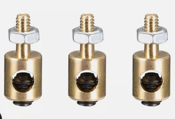
This is really what you want instead of bending the pushrods to fit directly into the control arms. Example pic. It’s easier to set these up and adjust them – I chose the hard route.

Sliced underneath the ailerons with a razor to fit in the control arms.

A few drops of CA, plop the control arms in, make sure they’re level with the wing, done.

Next challenge: glue the elevator mount and elevator on and simultaneously align it with the pod so it’s level.

Use any features of the kit to help you line this up. In my case, the elevator had a nice straight black line on it that I could line up with the flat top of the back of the pod.

Once I mocked it up level, I scratched a tiny line in the carbon with a pick on both the boom and the mount.

I chose to use CA for this, which frankly was a bit dangerous: it’s instantly sticky and offers no time to re-adjust the orientation of anything before it dries and hardens (unlike epoxy). I’d recommend using 5-minute epoxy for this instead, even though it can be a tiny bit heavier. I only had like 8 seconds before the glue became too stuck to adjust this when I slid it on, which is too tight of a window of time to handle delicate stuff like this.

I initially picked three HS-40 servos for this build. However, the elevator control movement was stickier than I expected it to be, and I worried that I’d epoxy in an HS-40 and it would burn out from not having the torque at 3.7v since this setup is going to run off a 1S LiPo. So I chose an HS-45 for the elevator instead of the HS-40. Regardless, I enlargened the horns here a tiny bit to accommodate the piano wire directly.

Aileron servos were CA’ed together first after checking fitment in the pod. Test the servos with a servo tester like this – neutralize the horns and make sure all is functioning well! I did this many times during the build process to make sure I wasn’t installing something backwards, or a servo that was not at neutral.

I settled on this setup in the pod: two HS-40s for the ailerons, and one HS-45 for the elevator. I used the design of the servos to my advantage and superglued them together like this. I had nothing in my shop to mount the servos on, so I intended to make them one block like this and glue them in. Normally, you’d have some sort of servo mount to go into the pod and mount the servos too, however primitive it is. I compensated for not having this by using a small piece of wood later in the build.

Launch peg was easy – a bit of CA, and clamps. This peg design is not really a peg at all and more of a handle. It glues to both bottom and top of the wing here for a solid connection.

With the elevator mount all dried, I cut a length of piano wire and ran it from the pod to the articulating control arm. I took the wire, made a nice O-shape, and slid it over the spring. Then the end of the spring was wrapped back up towards the top of the mount, as a backup in case the piano wire slipped. I took pliers and crushed the piano wire closer into the plastic, closing the “O” shape a bit, to add extra insurance that it won’t move. This isn’t perfect, and it’s totally bizarre, but it’ll hold.

The whole apparatus had more friction than I expected (even before the excess CA got into the joint) and required more torque from the servo moving it. I opted for an HS-45 over an HS-40.

I didn’t have pushrod tubing to keep the pushrod in place along the boom. Instead, I rolled scotch tape upside-down over it, making a smooth inner tube for the rod to move, then put a big piece of tape over the whole tube and around the boom. I did this a few times down the boom to route the elevator pushrod and keep it from bending away from the boom. This is a cheap solution, doesn’t look that great, and may not age well (scotch tape tends to disintegrate as it sees more sunlight), but it works fairly well.
I also measured and cut two pushrods for the ailerons at this time. I don’t have pictures of what these looked like, but make sure to bend the ends in the right direction. The aileron side should be bent so the wire sticks OUT (with plenty of excess so it can be curled a bit), away from the pod. This ensures that it won’t pop out. The servo side bend has to be perpendicular to the aileron bends, unlike the elevator which due to the servo mounting, is bent sideways to fit into the horn. This is hard to explain with just words, but as you measure, cut the wire and start bending, you’ll realize things have to go a certain way otherwise it just won’t all fit together. Buy a good amount of wire – 4 feet or more – so you have extra in case you need to make another pushrod.
Reminder: you could ignore the above paragraph if you had just bought pushrod connectors, which I should have done. In that case, the pushrods remain straight (no end-bending required, but you might have to bend the rods slightly to conform to the shape of the DLG/where the exit holes are from the pod) and slide through the connectors on the control arms and servo horns. They are held in place by small grub screws - normally 1.5mm hex size, so make sure you have that tool too.

As for batteries, I initially picked these two: a Li-Ion 650mAH 1S, and a LiPo 350mAH 1S. Both fit, but the Li-Ion was too heavy to have up front once I checked the CG (center of gravity) of the whole plane, so I opted for the LiPo.


Test fitting the servos and batteries in and again using the servo tester to make sure everything is aligned right / horns are on the right way, no weird issues with the servos like binding or friction against the sides of the pod, etc.


Notice I put some scotch tape under the servo horn of the HS-45 (which will be flat on the bottom of the boom, moreorless), so that epoxy didn’t get on the horn and mess with the servo’s operation. This piece of tape uses the same technique as the pushrod tubes on the boom – the part that’s near the horn is actually folded over itself so it won’t stick. A small tab of sticky-side was kept to hold it onto the servo.

Epoxy applied all over the bottom. Holding it while it dries and trying to keep the servos all level so that none of the horns of the aileron (upright) servos end up touching the pod cover or chafing on the sides of the pod. During this time I hooked up the servo tester on the elevator servo which is lying flat – I wanted to make sure the side of the servo horn wouldn’t chafe against the side of the pod. I used this piece of dowel to hold the servos in place while the glue dried to get my fingers out of the way so I could see the motion of the servo horn. :)

This cut of a wooden dowel I’m going to use as a top reinforcer for the servo block, considering I had nothing to mount them to that would fit underneath them or on the sides. I sanded the edges down so it would fit diagonally, adding more structure in case the elevator servo comes loose of its glue. The elevator servo is the weakest link of the block since it’s wider and laid flat, so it had less surface area for the epoxy to hold onto on the bottom.
Normally, this concern would be solved from the bottom up, and not top down like this. A servo mount would go under – or on the sides of – the servos. This is a… custom situation. :)


DLGs always have such tight fits in these little pods. The pushrods just glazed over my improvised wooden support beam here.

One of the benefits of using thicker piano wire is that I can just bend it how I like and it’ll hold the shape well, even under the torque of these smaller servos. Here I just bent one of the pushrods slightly so it wouldn’t chafe the other one at the point where they crossed. Simple.

You may notice that the whole servo block isn’t aligned straight with the rest of the pod. This is normal for DLG pods to use space as wisely as possible. The servo horns themselves on upright servos often are set up to be perpendicular to the sides of the boom, but don’t necessarily have to be. There are a number of ways I could have set up the servos here – I could have done them a lot more diagonally. When I cut the pushrods, I cut two the exact same size to make it easier to make adjustments as a set instead of individually.
This genius building technique failed due to unforseen circumstances below…
Servo Failure
Despite testing the servos over and over with the servo tester, one of them died immediately upon the epoxy drying, which was such insanely bad luck that I genuinely couldn’t believe it for a few minutes. But it was true, that one of the aileron servos started jittering only a mere breath into its life, and it couldn’t hold itself steady or move in either direction smoothly. I double-checked to make sure it wasn’t anything up with the linkages or radio, to no avail. It was the servo itself.
What to do? My options were I could either try to pry the super glue and epoxy apart and replace the servo, or mount up another one and just consider the dead servo… ballast. And that’s what I did.
 Well, I’m lucky it wasn’t the elevator servo, at least. Here’s 4 servos in a pod for a plane that only needs 3…

Adjusted the pushrod (on left in pic) a bit to accomodate the new servo mounting position for it. This is when those pushrod connectors I didn’t have would’ve made my life easier.


Wiring inside tiny DLG pods looks tough, but most of the time you can just push all the wires way up into the frontmost area of the pod where nothing else can really fit anyways.

The Li-Ion battery fits so nicely, but it is too heavy! Once I started checking the CG of the whole airplane, it became apparent I had to use the lighter LiPo battery.

Final step now that everything is checked twice over: curve the pushrod ends that connect to the servo horns so they won’t come out.

A tiny bit of threadlock on the wing bolts, and the wing is bolted on securely. The plane looks great but, where’s the rudder? I saved it for last since when working with the pod and what not it’s easy to damage the rudder that sticks out from underneath the boom.


Me nervously trying to determine if that’s an 89 degree angle, or a 90 degree angle. This time, I opted for the 5min epoxy so I had time to adjust it before the glue hardened.

Epoxy is drying, and the plane is looking great! I love the yellow color – it will look great against a clear blue sky.

All glue dried now, everything is nice and aligned.


The manual calls for a CG 70-75mm back from the leading edge of the wing. With the LiPo battery, it’s spot on.

Receiver goes flat underneath the battery. All the wires are squished into the absolute front of the pod’s nose.

All in all: 157 grams total weight. (Recommended 140-160). It’s on the heavy side, but within spec. Considering I have an entire extra servo mounted with epoxy that shouldn’t be in there (sigh…), I consider this a success weight-wise.

Look down the edge of the ailerons to make sure they are perfectly sub-trimmed into place. The wing should look FLAT from the top and bottom as seen below.


What a pretty little plane! This was quite the project. When a warm, calm day comes, I’ll take it out for a spin.
Update
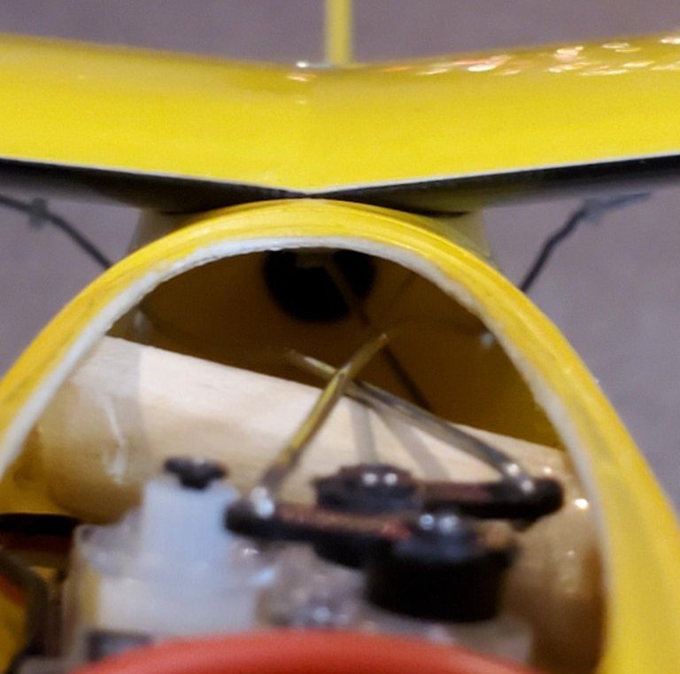
One issue I noticed after further inspection was that the elevator pushrod was stuck up over one of the aileron ones, which made the aileron slightly wiggle with the elevator’s motion.
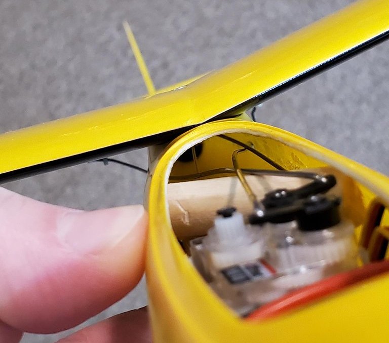
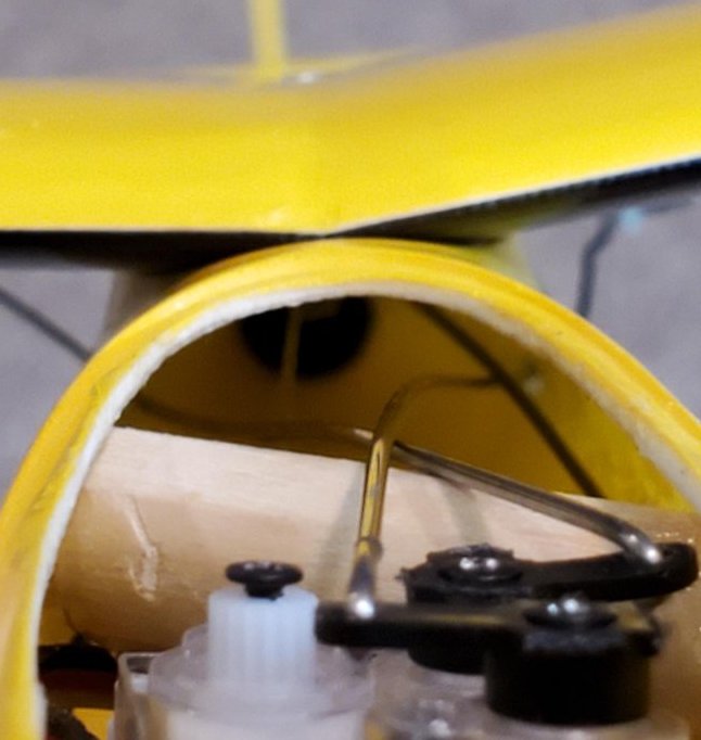
This was solved by unscrewing the servo horn and unhooking the pushrod at the aileron, and readjusting the routing of the pushrod. Easy.
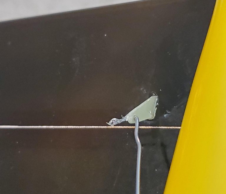
I also put small globs of hot glue on the ends of the pushrods at the aileron side, just as added security in case they somehow start slipping out. Hot glue is easy to pick off if need-be.
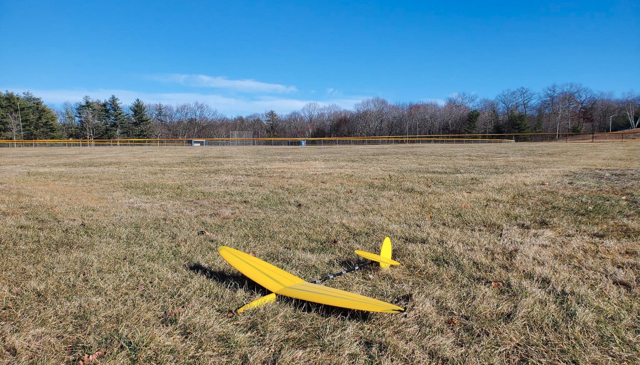
Third time out in the winter and caught a thermal! Flies well after some trimming. It’s so light!
Wishing you a great build, and trustworthy servos,
Daniel